
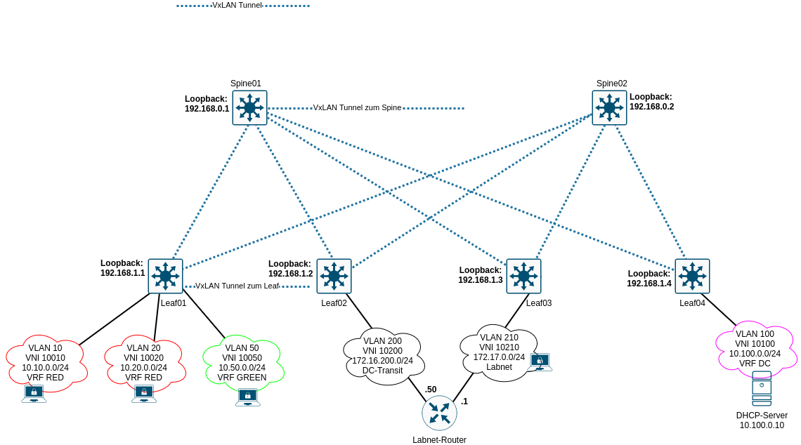
Nach Inbetriebnahme von Underlay- und Overlaynetzwerk können die Netze der Clients eingerichtet werden. Alle VLANs werden in den Spines geroutet. Nur in den Spines werden IRB-Interfaces eingerichtet. Alle VLANs erhalten zeitgleich eine VxLAN-ID. Es können diverse Routing-Instanzen konfiguriert werden, als auch diverse Switch-Instanzen. Je nach Konfiguration können entsprechend mehr als 4094 VLANs ermöglicht werden. Folgende Topologie soll konfiguriert werden:
Grundlegendes
Das Beispiel beinhaltet die Terminierung der VxLAN-Tunnel auf die Loopback Adressen der jeweiligen Geräte. Damit werden “nur” 4094 VLANs ermöglicht. Um der Sache dennoch etwas Komplexität zu verleihen, werden drei VRFs implementiert. Diese sollen im ersten Start keine Verbindung untereinander haben. Weiterhin wird ein VLAN für einen Router für “Labornetze” eingerichtet, welcher Zugriff auf das kommende Transitnetz besitzt. Der Router selber besitzt ein Labnetz, an welches Clients über Leafs angebunden sind.
Konfigurationsdaten
EVPN
Die VTEP Konfiguration wird auf die jeweiligen Loopback Adressen der Geräte konfiguriert. Als RD wird die Loopback Adresse mit einer “1” verwendet. Das RT ist die AS-Nummer mit einer “1”. Das VRF wird automatisch exportiert, damit nach Einrichtungen von VLANs diese sofort zur Verfügung stehen.
| System | RD | RT |
|---|---|---|
| Spine01 | 192.168.0.1:1 | target:65000:1 |
| Spine02 | 192.168.0.2:1 | target:65000:1 |
| Leaf01 | 192.168.1.1:1 | target:65000:1 |
| Leaf02 | 192.168.1.2:1 | target:65000:1 |
| Leaf03 | 192.168.1.3:1 | target:65000:1 |
| Leaf04 | 192.168.1.4:1 | target:65000:1 |
VLANs
| VLAN | VLAN-ID | VNI | IRB IP | Virtual Gateway | Route Distinguisher | Route Target | VRF |
|---|---|---|---|---|---|---|---|
| VL10 | 10 | 10010 | 10.10.0.254/24 | 10.10.0.1/24 | 192.168.0.1:101 target:65000:101 | RED | |
| VL20 | 20 | 10020 | 10.20.0.254/24 | 10.20.0.1/24 | 192.168.0.1:101 target:65000:101 | RED | |
| VL50 | 50 | 10050 | 10.50.0.254/24 | 10.50.0.1/24 | 192.168.0.1:102 target:65000:102 | GREEN | |
| VL100 | 100 | 10100 | 10.100.0.254/24 | 10.100.0.1/24 | 192.168.0.1:103 target:65000:103 | DC | |
| VL200 | 200 | 10200 | — | — | — | — | — |
| VL210 | 210 | 10210 | — | — | — | — | — |
Achtung: auf Spine02 muss der RD angepasst werden. Hier wird `192.168.0.2:xyz verwendet. Der RD ist nur auf dem Gerät entscheidend, der RT muss auf allen VPN-Verbindungen gleich sein, andernfalls könnten Routen übertragen werden, die nicht gewünscht sind.
Aufbau Route Distinguisher
Der Route Distinguisher baut sich anhand der Loopback Adresse lo0.0 (192.168.0.1) und des letzten Oktetts der für das VRF ausgewählten Loopback Adresse auf. Für VRF RED wird die Loopback Adresse lo0.101 mit 192.168.0.101 konfiguriert, für VRF GREEN Loopback lo0.102 mit 192.168.0.102, für VRF DC Loopback lo0.103 mit 192.168.0.103 verwendet. Hieraus abgeleitet ergeben sich die RDs.
Spine01 RD
| VRF | Loopback lo0.0 | Loopback Unit VRF | Loopback IP VRF | RD |
|---|---|---|---|---|
| RED | 192.168.0.1 | unit 101 | 192.168.0.101 | 192.168.0.1:101 |
| GREEN | 192.168.0.1 | unit 102 | 192.168.0.102 | 192.168.0.1:102 |
| DC | 192.168.0.1 | unit 103 | 192.168.0.103 | 192.168.0.1:103 |
Aufbau Route Targets
Die Route Targets bauen sich aus der AS Nummer des Overlaynetzes und dem letzten Oktett der Loopback Adressen des jeweiligen VRF auf.
| VRF | AS Nummer iBGP | Loopback IP VRF | RT |
|---|---|---|---|
| RED | 65000 | 192.168.0.101 | target:65000:101 |
| GREEN | 65000 | 192.168.0.102 | target:65000:101 |
| DC | 65000 | 192.168.0.103 | target:65000:101 |
Konfiguration Spines
EVPN - Spine01
1
2
3
4
5
6
7
8
9
10
11
12
13
14
15
16
17
edit switch-options
set vtep-source-interface lo0.0
set route-distinguisher 192.168.0.1:1
set vrf-target target:65000:1
set vrf-target auto

top edit protocols evpn

set encapsulation vxlan
set default-gateway no-gateway-community
set extended-vni-list all

top

set routing-options router-id 192.168.0.1

commit
EVPN - Spine02
1
2
3
4
5
6
7
8
9
10
11
12
13
14
15
edit switch-options
set vtep-source-interface lo0.0
set route-distinguisher 192.168.0.2:1
set vrf-target target:65000:1
set vrf-target auto

top edit protocols evpn

set encapsulation vxlan
set default-gateway no-gateway-community
set extended-vni-list all

top

set routing-options router-id 192.168.0.2
VLAN, VxLAN & IRB Interfaces - Spine01
1
2
3
4
5
6
7
8
9
10
11
12
13
14
15
16
17
18
19
20
21
22
23
24
25
26
27
28
29
30
31
32
33
34
35
36
37
38
39
40
41
42
43
44
45
46
47
48
49
50
51
52
53
54
55
56
57
58
59
60
61
62
63
64
65
66
67
68
69
70
71
72
73
74
75
76
77
78
79
edit vlans

edit VL10
set description "VLAN-10"
set vlan-id 10
set l3-interface irb.10
set vxlan vni 10010

up

edit VL20
set description "VLAN-20"
set vlan-id 20
set l3-interface irb.20
set vxlan vni 10020

up

edit VL50
set description "VLAN-50"
set vlan-id 50
set l3-interface irb.50
set vxlan vni 10050

up

edit VL100
set description "Datacenter"
set vlan-id 100
set l3-interface irb.100
set vxlan vni 10100

up

edit VL200
set description "DC-Transit"
set vlan-id 200
set vxlan vni 10200

up

edit VL210
set description "Labnet"
set vlan-id 210
set vxlan vni 10210

top edit interfaces irb

edit unit 10
set description "VLAN-10"
set family inet address 10.10.0.254/24 preferred virtual-gateway-address 10.10.0.1
set proxy-macip-advertisement
set virtual-gateway-accept-data

up

edit unit 20
set description "VLAN-20"
set family inet address 10.20.0.254/24 preferred virtual-gateway-address 10.20.0.1
set proxy-macip-advertisement
set virtual-gateway-accept-data

up

edit unit 50
set description "VLAN-50"
set family inet address 10.50.0.254/24 preferred virtual-gateway-address 10.50.0.1
set proxy-macip-advertisement
set virtual-gateway-accept-data

up

edit unit 100
set description "Datacenter"
set family inet address 10.100.0.254/24 preferred virtual-gateway-address 10.100.0.1
set proxy-macip-advertisement
set virtual-gateway-accept-data

commit
VLAN, VxLAN & IRB Interfaces - Spine02
1
2
3
4
5
6
7
8
9
10
11
12
13
14
15
16
17
18
19
20
21
22
23
24
25
26
27
28
29
30
31
32
33
34
35
36
37
38
39
40
41
42
43
44
45
46
47
48
49
50
51
52
53
54
55
56
57
58
59
60
61
62
63
64
65
66
67
68
69
70
71
72
73
74
75
76
77
78
79
edit vlans

edit VL10
set description "VLAN-10"
set vlan-id 10
set l3-interface irb.10
set vxlan vni 10010

up

edit VL20
set description "VLAN-20"
set vlan-id 20
set l3-interface irb.20
set vxlan vni 10020

up

edit VL50
set description "VLAN-50"
set vlan-id 50
set l3-interface irb.50
set vxlan vni 10050

up

edit VL100
set description "Datacenter"
set vlan-id 100
set l3-interface irb.100
set vxlan vni 10100

up

edit VL200
set description "DC-Transit"
set vlan-id 200
set vxlan vni 10200

up

edit VL210
set description "Labnet"
set vlan-id 210
set vxlan vni 10210

top edit interfaces irb

edit unit 10
set description "VLAN-10"
set family inet address 10.10.0.253/24 preferred virtual-gateway-address 10.10.0.1
set proxy-macip-advertisement
set virtual-gateway-accept-data

up

edit unit 20
set description "VLAN-20"
set family inet address 10.20.0.253/24 preferred virtual-gateway-address 10.20.0.1
set proxy-macip-advertisement
set virtual-gateway-accept-data

up

edit unit 50
set description "VLAN-50"
set family inet address 10.50.0.253/24 preferred virtual-gateway-address 10.50.0.1
set proxy-macip-advertisement
set virtual-gateway-accept-data

up

edit unit 100
set description "Datacenter"
set family inet address 10.100.0.253/24 preferred virtual-gateway-address 10.100.0.1
set proxy-macip-advertisement
set virtual-gateway-accept-data

commit
VRFs - Spine01
1
2
3
4
5
6
7
8
9
10
11
12
13
14
15
16
17
18
19
20
21
22
23
24
25
26
27
28
29
30
31
32
33
34
35
36
37
38
39
40
41
42
43
44
45
edit interfaces lo0 unit 101
set description VRF-RED
set family inet address 192.168.0.101/32

up
edit unit 102
set description VRF-GREEN
set family inet address 192.168.0.102/32

up
edit unit 103
set description VRF-DC
set family inet address 192.168.0.103/32


top edit routing-instances

edit RED
set description VRF-RED
set instance-type vrf
set interface irb.10
set interface irb.20
set interface lo0.101
set route-distinguisher 192.168.0.1:101
set vrf-target target:65000:101

up
edit GREEN
set description VRF-GREEN
set instance-type vrf
set interface irb.50
set interface lo0.102
set route-distinguisher 192.168.0.1:102
set vrf-target target:65000:102

up
edit DC
set description VRF-DC
set instance-type vrf
set interface irb.100
set interface lo0.103
set route-distinguisher 192.168.0.1:103
set vrf-target target:65000:103

commit
VRFs - Spine02
1
2
3
4
5
6
7
8
9
10
11
12
13
14
15
16
17
18
19
20
21
22
23
24
25
26
27
28
29
30
31
32
33
34
35
36
37
38
39
40
41
42
edit interfaces lo0 unit 101
set description VRF-RED
set family inet address 192.168.0.201/32

up
edit unit 102
set description VRF-GREEN
set family inet address 192.168.0.202/32

up
edit unit 103
set description VRF-DC
set family inet address 192.168.0.203/32

top edit routing-instances

edit RED
set description VRF-RED
set instance-type vrf
set interface irb.10
set interface irb.20
set interface lo0.101
set route-distinguisher 192.168.0.2:101
set vrf-target target:65000:101

up
edit GREEN
set description VRF-GREEN
set instance-type vrf
set interface irb.50
set interface lo0.102
set route-distinguisher 192.168.0.2:102
set vrf-target target:65000:102

up
edit DC
set description VRF-DC
set instance-type vrf
set interface irb.100
set interface lo0.103
set route-distinguisher 192.168.0.2:103
set vrf-target target:65000:103
Konfiguration Leafs
EVPN - Leaf01
1
2
3
4
5
6
7
8
9
10
11
12
13
14
set routing-options router-id 192.168.1.1

edit protocols evpn
set encapsulation vxlan
set extended-vni-list all

top edit switch-options

set vtep-source-interface lo0.0
set route-distinguisher 192.168.1.1:1
set vrf-target target:65000:1
set vrf-target auto

commit
EVPN - Leaf02
1
2
3
4
5
6
7
8
9
10
11
12
13
14
set routing-options router-id 192.168.1.2

edit protocols evpn
set encapsulation vxlan
set extended-vni-list all

top edit switch-options

set vtep-source-interface lo0.0
set route-distinguisher 192.168.1.2:1
set vrf-target target:65000:1
set vrf-target auto

commit
EVPN - Leaf03
1
2
3
4
5
6
7
8
9
10
11
12
13
14
set routing-options router-id 192.168.1.3

edit protocols evpn
set encapsulation vxlan
set extended-vni-list all

top edit switch-options

set vtep-source-interface lo0.0
set route-distinguisher 192.168.1.3:1
set vrf-target target:65000:1
set vrf-target auto

commit
EVPN - Leaf04
1
2
3
4
5
6
7
8
9
10
11
12
13
14
set routing-options router-id 192.168.1.4

edit protocols evpn
set encapsulation vxlan
set extended-vni-list all

top edit switch-options

set vtep-source-interface lo0.0
set route-distinguisher 192.168.1.4:1
set vrf-target target:65000:1
set vrf-target auto

commit
VLAN, VxLAN - Leaf01 - Leaf04
1
2
3
4
5
6
7
8
9
10
11
12
13
14
15
16
17
18
19
20
21
22
23
24
25
26
27
28
29
30
31
32
33
34
35
36
37
38
39
40
41
42
43
edit vlans

edit VL10
set description "VLAN-10"
set vlan-id 10
set vxlan vni 10010

up

edit VL20
set description "VLAN-20"
set vlan-id 20
set vxlan vni 10020

up

edit VL50
set description "VLAN-50"
set vlan-id 50
set vxlan vni 10050

up

edit VL100
set description "Datacenter"
set vlan-id 100
set vxlan vni 10100

up

edit VL200
set description "DC-Transit"
set vlan-id 200
set vxlan vni 10200

up

edit VL210
set description "Labnet"
set vlan-id 210
set vxlan vni 10210

commit
show Befehle
Die IRB-Interfaces müssen up / up sein.
1
2
3
4
5
6
7
8
9
10
11
root@Spine02> show interfaces terse irb
Interface Admin Link Proto Local Remote
irb    up up
irb.10 up up inet 10.10.0.1/24
                  10.10.0.253/24
irb.20 up up inet 10.20.0.1/24
                  10.20.0.253/24
irb.50 up up inet 10.50.0.1/24
                  10.50.0.253/24
irb.100 up up inet 10.100.0.1/24
                   10.100.0.253/24
Tunnel Endpunkte müssen up / up sein.
1
2
3
4
5
root@Spine02> show interfaces terse vtep
Interface Admin Link Proto Local Remote
vtep       up up
vtep.32768 up up
vtep.32770 up up eth-switch
Im ARP müssen sich die IP-Adressen vom Spine01 befinden.
1
2
3
4
5
6
7
8
9
10
root@Spine02> show arp no-resolve
MAC Address Address Interface Flags
02:05:86:71:a9:00 10.10.0.254 irb.10 [vtep.32770] none
02:05:86:71:a9:00 10.20.0.254 irb.20 [vtep.32770] none
02:05:86:71:a9:00 10.50.0.254 irb.50 [vtep.32770] none
02:05:86:71:a9:00 10.100.0.254 irb.100 [vtep.32770] none
02:05:86:71:02:07 192.168.10.5 xe-0/0/0.0 none
02:05:86:71:af:07 192.168.10.9 xe-0/0/1.0 none
02:05:86:71:ea:07 192.168.10.13 xe-0/0/2.0 none
02:05:86:71:f1:07 192.168.10.17 xe-0/0/3.0 none
Die Switchingtabelle kann für bspw. VLAN 50 abgefragt werden.
1
2
3
4
5
6
7
8
9
10
root@Spine02> show ethernet-switching table vlan-id 50

MAC flags (S - static MAC, D - dynamic MAC, L - locally learned, P - Persistent static
SE - statistics enabled, NM - non configured MAC, R - remote PE MAC, O - ovsdb MAC)

Ethernet switching table : 2 entries, 2 learned
Routing instance : default-switch
Vlan MAC MAC Logical Active name address flags interface source
VL50 00:00:5e:00:01:01 DR esi.1797 05:00:00:fd:e8:00:00:27:42:00
VL50 02:05:86:71:a9:00 D vtep.32770 192.168.0.1
Die Remote-Endpunkte sollten die vorher konfigurierten VNIs auflisten.
1
2
3
4
5
6
7
8
9
10
11
12
root@Spine02> show ethernet-switching vxlan-tunnel-end-point remote
Logical System Name Id SVTEP-IP IFL L3-Idx SVTEP-Mode
<default> 0 192.168.0.2 lo0.0 0
RVTEP-IP L2-RTT IFL-Idx NH-Id RVTEP-Mode
192.168.0.1 default-switch 566 1794 RNVE
VNID MC-Group-IP
10100 0.0.0.0
10020 0.0.0.0
10050 0.0.0.0
10010 0.0.0.0
10200 0.0.0.0
10210 0.0.0.0
Es müssen neben inet.0 drei weitere Routingtabellen für die jeweiligen VRFs auftauchen.
1
2
3
4
5
6
7
8
9
10
11
12
13
14
15
root@Spine02# run show route table ?
Possible completions:
<table> Name of routing table
:vxlan.inet.0
DC.inet.0
DC.inet6.0
GREEN.inet.0
GREEN.inet6.0
RED.inet.0
RED.inet6.0
__default_evpn__.evpn.0
bgp.evpn.0
default-switch.evpn.0
inet.0
inet6.0
Konfiguration - Blöcke
1
2
3
4
5
6
7
8
9
10
11
12
13
14
15
16
17
18
19
20
21
22
23
24
25
26
27
28
29
30
31
32
33
34
35
36
37
38
39
40
41
42
43
44
45
46
47
48
49
50
51
52
53
54
55
56
57
58
59
60
61
62
63
64
65
66
67
68
69
70
71
72
73
74
75
76
77
78
79
80
81
82
83
84
85
86
87
88
89
90
91
92
93
94
95
96
97
98
99
100
101
102
103
104
105
106
107
108
109
110
111
112
113
114
115
116
117
118
119
120
121
122
123
124
125
126
127
128
129
130
131
132
133
134
135
136
root@Spine01# show switch-options
vtep-source-interface lo0.0;
route-distinguisher 192.168.0.1:1;
 vrf-target {
  target:65000:1;
  auto;
}

root@Spine01# show protocols evpn
encapsulation vxlan;
default-gateway no-gateway-community;
extended-vni-list all;

root@Spine01# show vlans
 VL10 {
  description VLAN-10;
  vlan-id 10;
  l3-interface irb.10;
  vxlan {
  vni 10010;
 }
}
VL100 {
  description Datacenter;
  vlan-id 100;
  l3-interface irb.100;
  vxlan {
  vni 10100;
 }
}
VL20 {
  description VLAN-20;
  vlan-id 20;
  l3-interface irb.20;
  vxlan {
  vni 10020;
 }
}
VL200 {
  description DC-Transit;
  vlan-id 200;
  vxlan {
  vni 10200;
 }
}
VL210 {
  description Labnet;
  vlan-id 210;
  vxlan {
  vni 10210;
 }
}
VL50 {
  description VLAN-50;
  vlan-id 50;
  l3-interface irb.50;
  vxlan {
  vni 10050;
 }
}
default {
  vlan-id 1;
}

root@Spine01# show interfaces irb
 unit 10 {
  proxy-macip-advertisement;
  virtual-gateway-accept-data;
  description VLAN-10;
  family inet {
  address 10.10.0.254/24 {
   preferred;
   virtual-gateway-address 10.10.0.1;
   }
  }
}
unit 20 {
  proxy-macip-advertisement;
  virtual-gateway-accept-data;
  description VLAN-20;
  family inet {
   address 10.20.0.254/24 {
   preferred;
   virtual-gateway-address 10.20.0.1;
  }
 }
}
unit 50 {
  proxy-macip-advertisement;
  virtual-gateway-accept-data;
  description VLAN-50;
  family inet {
  address 10.50.0.254/24 {
   preferred;
   virtual-gateway-address 10.50.0.1;
  }
 }
}
unit 100 {
  proxy-macip-advertisement;
  virtual-gateway-accept-data;
  description Datacenter;
  family inet {
   address 10.100.0.254/24 {
   preferred;
   virtual-gateway-address 10.100.0.1;
  }
 }
}

root@Spine01# show routing-instances
DC {
  description VRF-DC;
  instance-type vrf;
  interface irb.100;
  interface lo0.103;
  route-distinguisher 192.168.0.1:103;
  vrf-target target:65000:103;
 }
GREEN {
  description VRF-GREEN;
  instance-type vrf;
  interface irb.50;
  interface lo0.102;
  route-distinguisher 192.168.0.1:102;
  vrf-target target:65000:102;
 }
RED {
  description VRF-RED;
  instance-type vrf;
  interface irb.10;
  interface irb.20;
  interface lo0.101;
  route-distinguisher 192.168.0.1:101;
  vrf-target target:65000:101;
 }