
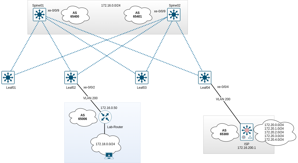
Um Zugriff auf Clients und Server sowohl in als auch aus dem Datacenter hinaus zu ermöglichen, müssen die Spines einen Uplink zu einem Provider / Router / Gatway besitzen. Im Beispiel wird der Router “ISP” angebunden. Folgende Topologie wird konfiguriert:
Grundlegendes
Die Routingkonfiguration findet im VRF WAN statt. Es sollen exemplarisch eine statische Route, eine direkte Route, eine zusammengefasste Route und eine BGP-Route zum ISP gesendet werden. Spine02 soll zudem eine schlechtere Localpreference und einen schlechteren MED-Wert zum ISP senden, damit diese Routen nur bei Ausfall von Spine01 verwendet werden. Alle 172.20er Netze des ISP sollen angenommen werden. Diese sollen im Datacenter bereitgestellt werden, jedoch nicht im VRF RED und GREEN. Die erlernte Route vom Labrouter soll nur im VRF GREEN und im ISP-Router zur Verfügung stehen.
Konfigurationsdaten
| Gerät | Interface | IP | ASN |
|---|---|---|---|
| Spine01 | xe-0/0/9 | 172.16.200.254/24 | 65400 |
| Spine02 | xe-0/0/9 | 172.16.200.253/24 | 65401 |
| ISP | Ethernet0/0 | 172.16.200.1/24 | 65300 |
| Lab-Router | eth0 | 172.16.200.50/24 | 65006 |
Konfiguration BGP - Spine01
1
2
3
4
5
6
7
8
9
10
11
12
13
14
15
16
17
18
19
20
21
22
23
24
25
26
27
28
29
30
31
32
33
34
35
36
37
38
39
40
41
42
43
44
45
46
47
48
49
50
51
52
53
54
55
56
57
58
59
60
61
62
top edit routing-instances WAN protocols bgp

set family inet unicast
set family inet unicast prefix-limit maximum 1000
set family inet unicast prefix-limit teardown

edit group ISP
set description "Connection-2-ISP"
set local-as 65400
set graceful-restart
set log-updown
set export bgp_vrf-wan_bgp-out

set neighbor 172.16.200.1 description "ISP"
set neighbor 172.16.200.1 peer-as 65300
set neighbor 172.16.200.1 authentication-key password
Konfiguration Policy - Spine01
top edit policy-options policy-statement bgp_vrf-wan_bgp-out

edit term summary
set from protocol aggregate
then metric 200
set then accept
up

edit term direct
set from protocol direct
set from route-filter 192.168.200.0/24 orlonger
then metric 200
set then accept
up

edit term static
set from protocol static
set from route-filter 10.200.0.0/24 orlonger
then metric 200
set then accept
up

edit term from-bgp
set from protocol bgp
set from community labrouter
then metric 200
set then accept

up
up

community labrouter members 65006:23
Konfiguration Routen für BGP - Spine01
top edit routing-instances WAN routing-options static

set route 192.168.100.0/24 discard
set route 192.168.101.0/24 discard
set route 10.200.0.0/25 discard

up

edit routing-options aggregate
set route 192.168.100.0/23

commit
Peering - Spine01
Der ISP-Router muss jetzt im VRF WAN auftauchen.
1
2
3
4
5
6
7
8
9
10
11
root@Spine01# run show bgp summary instance WAN
Threading mode: BGP I/O
Groups: 1 Peers: 1 Down peers: 0
Table Tot Paths Act Paths Suppressed History Damp State Pending
WAN.inet.0
5 5 0 0 0 0
WAN.mdt.0
0 0 0 0 0 0
Peer AS InPkt OutPkt OutQ Flaps Last Up/Dwn State|#Active/Received/Accepted/Damped...
172.16.200.1 65300 42 40 0 0 17:34 Establ
WAN.inet.0: 5/5/5/0
Vom ISP sollten diverse 172.20er Netze propagiert werden.
1
2
3
4
5
6
7
8
9
10
11
12
13
14
15
16
17
18
19
20
root@Spine01# run show route table WAN.inet.0 protocol bgp

WAN.inet.0: 17 destinations, 17 routes (17 active, 0 holddown, 0 hidden)
+ = Active Route, - = Last Active, * = Both

172.20.0.0/24 *[BGP/170] 00:19:43, MED 0, localpref 100
AS path: 65300 I, validation-state: unverified
> to 172.16.0.1 via irb.99
172.20.1.0/24 *[BGP/170] 00:19:43, MED 0, localpref 100
AS path: 65300 I, validation-state: unverified
> to 172.16.0.1 via irb.99
172.20.2.0/24 *[BGP/170] 00:19:43, MED 0, localpref 100
AS path: 65300 I, validation-state: unverified
> to 172.16.0.1 via irb.99
172.20.3.0/24 *[BGP/170] 00:19:43, MED 0, localpref 100
AS path: 65300 I, validation-state: unverified
> to 172.16.0.1 via irb.99
172.20.4.0/24 *[BGP/170] 00:19:43, MED 0, localpref 100
AS path: 65300 I, validation-state: unverified
> to 172.16.0.1 via irb.99
Auf Seiten des ISP sollten jetzt Routen vom Spine01 (siehe Policy) auftauchen.
1
2
3
4
5
6
7
8
9
10
11
ISP#sh ip bgp
BGP table version is 47, local router ID is 172.20.0.1
Network Next Hop Metric LocPrf Weight Path
*> 10.200.0.0/25 172.16.0.100 0 65400 i
*> 172.20.0.0/24 0.0.0.0 0 32768 i
*> 172.20.1.0/24 0.0.0.0 0 32768 i
*> 172.20.2.0/24 0.0.0.0 0 32768 i
*> 172.20.3.0/24 0.0.0.0 0 32768 i
*> 172.20.4.0/24 0.0.0.0 0 32768 i
*> 192.168.100.0/23 172.16.0.100 0 65400 i
*> 192.168.200.0 172.16.0.100 0 65400 i
Konfiguration BGP - Spine02
1
2
3
4
5
6
7
8
9
10
11
12
13
14
15
16
17
18
19
20
21
22
23
24
25
26
27
28
29
30
31
32
33
34
35
36
37
38
39
40
41
42
43
44
45
46
47
48
49
50
51
52
53
54
55
56
57
58
59
60
61
62
63
top edit routing-instances WAN protocols bgp

set family inet unicast
set family inet unicast prefix-limit maximum 1000
set family inet unicast prefix-limit teardown

edit group ISP
set description "Connection-2-ISP"
set local-as 65401
set graceful-restart
set log-updown
set export bgp_vrf-wan_bgp-out
set local-preference 90

set neighbor 172.16.200.1 description "ISP"
set neighbor 172.16.200.1 peer-as 65300
set neighbor 172.16.200.1 authentication-key password
Konfiguration Policy - Spine02
top edit policy-options policy-statement bgp_vrf-wan_bgp-out

edit term summary
set from protocol aggregate
set then local-preference 90
set then accept
up

edit term direct
set from protocol direct
set from route-filter 192.168.200.0/24 orlonger
set then local-preference 90
set then accept
up

edit term static
set from protocol static
set from route-filter 10.200.0.0/24 orlonger
set then local-preference 90
set then accept
up

edit term from-bgp
set from protocol bgp
set from community labrouter
set then local-preference 90
set then accept

up
up

community labrouter members 65006:23
Konfiguration Routen für BGP - Spine02
top edit routing-instances WAN routing-options static

set route 192.168.100.0/24 discard
set route 192.168.101.0/24 discard
set route 10.200.0.0/25 discard

up

edit routing-options aggregate
set route 192.168.100.0/23

commit
Peering - Spine02
Der Router ISP sollte jetzt ebenfalls in Spine02 auftauchen.
1
2
3
4
5
6
7
8
9
10
11
root@Spine02> show bgp summary instance WAN
Threading mode: BGP I/O
Groups: 1 Peers: 1 Down peers: 0
Table Tot Paths Act Paths Suppressed History Damp State Pending
WAN.mdt.0
0 0 0 0 0 0
WAN.inet.0
5 5 0 0 0 0
Peer AS InPkt OutPkt OutQ Flaps Last Up/Dwn State|#Active/Received/Accepted/Damped...
172.16.200.1 65300 448 448 0 8 3:23:32 Establ
WAN.inet.0: 5/5/5/0
Es sollten Netze vom ISP sichtbar sein.
1
2
3
4
5
6
7
8
9
10
11
12
13
14
15
16
17
18
19
20
root@Spine02> show route table WAN.inet.0 protocol bgp

WAN.inet.0: 17 destinations, 17 routes (17 active, 0 holddown, 0 hidden)
+ = Active Route, - = Last Active, * = Both

172.20.0.0/24 *[BGP/170] 03:24:26, MED 0, localpref 100
AS path: 65300 I, validation-state: unverified
> to 172.16.0.1 via irb.99
172.20.1.0/24 *[BGP/170] 03:24:26, MED 0, localpref 100
AS path: 65300 I, validation-state: unverified
> to 172.16.0.1 via irb.99
172.20.2.0/24 *[BGP/170] 03:24:26, MED 0, localpref 100
AS path: 65300 I, validation-state: unverified
> to 172.16.0.1 via irb.99
172.20.3.0/24 *[BGP/170] 03:24:26, MED 0, localpref 100
AS path: 65300 I, validation-state: unverified
> to 172.16.0.1 via irb.99
172.20.4.0/24 *[BGP/170] 03:24:26, MED 0, localpref 100
AS path: 65300 I, validation-state: unverified
> to 172.16.0.1 via irb.99
Peering mit dem Labrouter
Damit der Labrouter mit den Spines BGP-Routen austauschen kann, muss dieser ins VLAN 200 zugreifen. Dies wird über einen Accessport am Leaf02 realisiert.
Konfiguration Leaf02
1
2
3
4
5
6
7
8
9
10
11
12
edit vlans VL200
set description DC-Transit
set vlan-id 200
set vxlan vni 10200

top edit interfaces xe-0/0/2
set description "Lab-Router"
delete unit 0 family inet
set unit 0 family ethernet-switching interface-mode access
set unit 0 family ethernet-switching vlan members VL200

commit
Damit der Client ebenfalls Zugriff erhält, werden zwei Accessports am Leaf03 konfiguriert. Uplink des Labrouters und Uplink eines “normalen” Clientsystems.
Konfiguration Leaf03
1
2
3
4
5
6
7
8
9
10
11
12
13
edit interfaces xe-0/0/2 unit 0
set description "Uplink-MGM-Router"
delete family inet
set family ethernet-switching interface-mode access
set family ethernet-switching vlan members VL210

edit interfaces xe-0/0/4 unit 0
set description "LabRechner"
delete family inet
set family ethernet-switching interface-mode access
set family ethernet-switching vlan members VL210

commit
Konfiguration Spine01 & Spine02
Auf beiden Spines muss der BGP-Prozess um den Labrouter erweitert werden.
1
2
3
4
5
6
7
edit routing-instances WAN protocols bgp group ISP

set neighbor 172.16.200.50 description Labrouter
set neighbor 172.16.200.50 peer-as 65006
set neighbor 172.16.200.50 authentication-key password

commit
Anschließend wird die Route des Labors in der WAN-Routingtabelle auftauchen.
1
2
3
4
5
6
7
8
9
10
11
root@Spine01# run show route table WAN
[...]

172.18.0.0/24 *[BGP/170] 00:18:53, MED 1, localpref 100
AS path: 65006 I, validation-state: unverified
> to 172.16.200.50 via irb.200
[BGP/170] 00:18:54, localpref 100, from 172.16.200.1
AS path: 65300 65401 65006 I, validation-state: unverified
> to 172.16.200.50 via irb.200

[...]
Durch Einstellung des MED sollten die Routen nicht in zweifacher Form auftauchen. Sollte dies der Fall sein, werden alle Pfade aufgelistet, wie bspw.:
1
2
3
4
5
6
7
8
 10.200.0.0/25 *[Static/5] 01:49:01
Discard
[BGP/170] 00:46:55, localpref 100, from 172.16.200.50
AS path: 65006 65401 I, validation-state: unverified
> to 172.16.200.253 via irb.200
[BGP/170] 00:02:20, localpref 100, from 172.16.200.1
AS path: 65300 65401 I, validation-state: unverified
> to 172.16.200.253 via irb.200
Dies ist grundsätzlich nicht falsch, aber in diesem Beispiel nicht notwendig. Der Pfad 65300-65401 kann mittels MED entfernt werden, da Spine01 das Netz lokal besitzt. Der Pfad 65006-65401 kann mittels Filter auf dem Labrouter entfernt werden. Der Router braucht lediglich die Route 172.18.0.0/24 zu propagieren, die Routen des ISP muss er nicht exportieren.
Damit können die Routen im Datacenter verteilt werden.
Labnetz ins VRF GREEN
Die rib-group vrf-wan-export muss um GREEN.inet.0 erweitert werden, anschließend wird die Policy RIB-vrf-wan-export erweitern und die rib-group direkt in den Routingoptionen vom VRF WAN eingetragen.
1
2
3
4
5
6
7
8
9
10
11
12
13
top edit routing-options
set rib-groups vrf-wan-export import-rib GREEN.inet.0

top edit policy-options policy-statement RIB-vrf-wan-export
edit term 3
set from protocol bgp route-filter 172.18.0.0/16 orlonger
set to rib GREEN.inet.0
set then accept

top edit routing-instances WAN protocols bgp group ISP
set family inet unicast rib-group vrf-wan-export

commit
Damit ist das Labornetz im VRF GREEN.
1
2
3
4
5
6
7
8
9
10
11
12
13
14
15
16
17
18
root@Spine01# run show route table GREEN

GREEN.inet.0: 6 destinations, 7 routes (6 active, 0 holddown, 0 hidden)
+ = Active Route, - = Last Active, * = Both

10.50.0.0/24 *[Direct/0] 03:17:55
> via irb.50
10.50.0.1/32 *[Local/0] 03:17:55
Local via irb.50
10.50.0.254/32 *[Local/0] 03:17:55
Local via irb.50
10.100.0.0/24 *[Direct/0] 03:17:55
> via irb.100
172.18.0.0/24 *[BGP/170] 00:06:17, MED 1, localpref 100
AS path: 65006 I, validation-state: unverified
> to 172.16.200.50 via irb.200
192.168.0.102/32 *[Direct/0] 03:21:48
> via lo0.102
Anschließend sollte eine Rückroute erstellt werden, andernfalls kann in das Labornetz kein Zugriff erfolgen.
Rückroute Labnetz auf VRF GREEN
Mittels neuer rib-group wird die Routingtabelle GREEN.inet.0 exportiert und das Netz 10.50.0.0/24 in WAN.inet.0 importiert. Anschließend wird das Netz per BGP exportiert.
1
2
3
4
5
6
7
8
9
10
11
12
13
14
15
16
edit routing-options
set rib-groups vrf-green-export import-rib GREEN.inet.0
set rib-groups vrf-green-export import-rib WAN.inet.0
set rib-groups vrf-green-export import-policy RIB-vrf-green-export

top edit policy-options policy-statement RIB-vrf-green-export
edit term 1
set from protocol direct
set from route-filter 10.50.0.0/24 exact
set to rib WAN.inet.0
set then accept

top edit routing-instances GREEN routing-options
set interface-routes rib-group inet vrf-green-export

commit
Damit liegt das Netz im VRF WAN.
1
2
3
4
5
6
7
root@Spine01# run show route table WAN 10.50.0.0

WAN.inet.0: 22 destinations, 31 routes (22 active, 0 holddown, 0 hidden)
+ = Active Route, - = Last Active, * = Both

10.50.0.0/24 *[Direct/0] 00:04:13
> via irb.50
Jetzt wird das Netz per BGP exportiert.
1
2
3
4
top edit policy-options policy-statement bgp_vrf-wan_bgp-out term direct
set from route-filter 10.50.0.0/24 exact

commit
Der Client im VRF GREEN kann jetzt in das Labnetz pingen.
1
2
3
4
5
6
7
20GRE1> ping 172.18.0.50

84 bytes from 172.18.0.50 icmp_seq=1 ttl=62 time=696.591 ms
84 bytes from 172.18.0.50 icmp_seq=2 ttl=62 time=514.463 ms
84 bytes from 172.18.0.50 icmp_seq=3 ttl=62 time=424.280 ms
84 bytes from 172.18.0.50 icmp_seq=4 ttl=62 time=616.057 ms
84 bytes from 172.18.0.50 icmp_seq=5 ttl=62 time=500.356 ms
Und umgekehrt kann das Labnetz ins VRF GREEN pingen.
1
2
3
4
5
6
7
LabR1> ping 10.50.0.22

84 bytes from 10.50.0.22 icmp_seq=1 ttl=62 time=574.659 ms
84 bytes from 10.50.0.22 icmp_seq=2 ttl=62 time=526.114 ms
84 bytes from 10.50.0.22 icmp_seq=3 ttl=62 time=518.889 ms
84 bytes from 10.50.0.22 icmp_seq=4 ttl=62 time=419.123 ms
84 bytes from 10.50.0.22 icmp_seq=5 ttl=62 time=336.846 ms
Problem bei dieser Lösung
Durch den Export des Netzes 10.50.0.0/24 in den Spines, wird dieses ebenfalls durch den ISP-Router gelernt. Dies kann auf den Spines durch eine weitere Policy verhindert werden. Die Policy nennt sich bgp_vrf-wan_bgp-out-ISP und wird direkt im neighbor-Statement des ISP-Routers aktiviert.
1
2
3
4
5
6
7
8
9
10
top edit policy-options
copy policy-statement bgp_vrf-wan_bgp-out to policy-statement bgp_vrf-wan_bgp-out-ISP
edit policy-statement bgp_vrf-wan_bgp-out-ISP
delete term direct from route-filter 10.50.0.0/24 exact

top edit routing-instances WAN protocols bgp
edit group ISP neighbor 172.16.200.1
set export bgp_vrf-wan_bgp-out-ISP

commit
Alle Netze des ISP ins VRF DC
Da die Routingtabelle des DC bereits in den rib-groups konfiguriert wurde, wird lediglich die Policy RIB-vrf-wan-export erweitert.
1
2
3
4
5
6
top edit policy-options policy-statement RIB-vrf-wan-export term 4
set from route-filter 172.20.0.0/16 orlonger
set to rib DC.inet.0
set then accept

commit
Die Routingtabelle wurde um die Routen des ISP erweitert.
1
2
3
4
5
6
root@Spine01# run show route table DC | match 172.20
172.20.0.0/24 *[BGP/170] 00:01:56, MED 0, localpref 100
172.20.1.0/24 *[BGP/170] 00:01:56, MED 0, localpref 100
172.20.2.0/24 *[BGP/170] 00:01:56, MED 0, localpref 100
172.20.3.0/24 *[BGP/170] 00:01:56, MED 0, localpref 100
172.20.4.0/24 *[BGP/170] 00:01:56, MED 0, localpref 100
Damit wären die Peerings fertiggestellt.
Konfigurationsblöcke
1
2
3
4
5
6
7
8
9
10
11
12
13
14
15
16
17
18
19
20
21
22
23
24
25
26
27
28
29
30
31
32
33
34
35
36
37
38
39
40
41
42
43
44
45
46
47
48
49
50
51
52
53
54
55
56
57
58
59
60
61
62
63
64
65
66
67
68
69
70
71
72
73
74
75
76
77
78
79
80
81
82
83
84
85
86
87
88
89
90
91
92
93
94
95
96
97
98
99
100
101
102
103
104
105
106
107
108
109
110
111
112
113
114
115
116
117
118
119
120
121
122
123
124
125
126
127
128
129
130
131
132
133
134
135
136
137
138
139
140
141
142
143
144
145
146
147
148
149
150
151
152
153
154
155
156
157
158
159
160
161
162
163
164
165
166
167
168
root@Spine01# show
bgp {
  family inet {
   unicast {
    prefix-limit {
     maximum 1000;
     teardown;
    }
   }
  }
group ISP {
 description Connection-2-ISP;
 log-updown;
 family inet {
  unicast {
   rib-group vrf-wan-export;
  }
 }
 export bgp_vrf-wan_bgp-out;
 local-as 65400;
 graceful-restart;
 neighbor 172.16.200.1 {
  description ISP;
  authentication-key "$9$5TnCtpBESe0BWxNdg4.P5T39"; ## SECRET-DATA
  export bgp_vrf-wan_bgp-out-ISP;
  peer-as 65300;
 }
 neighbor 172.16.200.50 {
  description Labrouter;
  authentication-key "$9$8lZL-wY2aUi.4a5Fn/0OKM8LNb"; ## SECRET-DATA
  peer-as 65006;
 }
 }
}

root@Spine01# show policy-statement bgp_vrf-wan_bgp-out
term summary {
 from protocol aggregate;
 then {
  metric 200;
  accept;
 }
}
term direct {
 from {
  protocol direct;
  route-filter 192.168.200.0/24 orlonger;
  route-filter 10.50.0.0/24 exact;
 }
 then {
  metric 200;
  accept;
 }
}
term static {
 from {
  protocol static;
  route-filter 10.200.0.0/24 orlonger;
 }
 then {
  metric 200;
  accept;
 }
}
term from-bgp {
 from {
  protocol bgp;
  community labrouter;
 }
then {
  metric 200;
  accept;
 }
}

root@Spine01# show policy-statement bgp_vrf-wan_bgp-out-ISP
term summary {
 from protocol aggregate;
 then {
  metric 200;
  accept;
 }
}
term direct {
 from {
  protocol direct;
  route-filter 192.168.200.0/24 orlonger;
 }
then {
 metric 200;
 accept;
}
}
term static {
 from {
  protocol static;
  route-filter 10.200.0.0/24 orlonger;
 }
then {
  metric 200;
  accept;
 }
}
term from-bgp {
 from {
  protocol bgp;
  community labrouter;
  }
then {
  metric 200;
  accept;
 }
}

root@Spine01# show routing-options
static {
 route 0.0.0.0/0 {
 next-hop 172.16.0.1;
 metric 1;
}
 route 192.168.100.0/24 discard;
 route 192.168.101.0/24 discard;
 route 10.200.0.0/25 discard;
 rib-group vrf-wan-export;
}
interface-routes {
 rib-group inet vrf-wan-export;
}
aggregate {
 route 192.168.100.0/23;
}
auto-export {
 family inet {
  unicast;
 }
}

root@Spine01# show GREEN routing-options
interface-routes {
 rib-group inet vrf-green-export;
}
auto-export {
 family inet {
  unicast;
 }
}

root@Spine01# show policy-statement RIB-vrf-green-export
term 1 {
 from {
  protocol direct;
  route-filter 10.50.0.0/24 exact;
 }
to rib WAN.inet.0;
then accept;
}

root@Spine01# show routing-options
rib-groups {
 vrf-wan-export {
  import-rib [ WAN.inet.0 DC.inet.0 RED.inet.0 GREEN.inet.0 ];
  import-policy RIB-vrf-wan-export;
 }
vrf-green-export {
  import-rib [ GREEN.inet.0 WAN.inet.0 ];
  import-policy RIB-vrf-green-export;
 }
}