
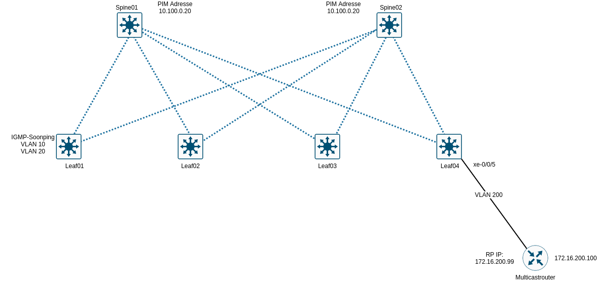
Multicastrouting ist eine Sache für sich und als komplex anzusehen. Um den Datenverkehr zu optimieren, müssen einige Konfigurationen in den Spines und Leafs durchgeführt werden. Andernfalls fließt Multicast von jedem Leaf über die Spines zu jedem anderen Leaf. Folgende Topologie soll konfiguriert werden.
Grundlegendes
Es gibt verschiedene Variationen Multicastrouting einzurichten. In den folgenden Beispielen werden beide Spines für Inter-VLAN Multicastrouting eingerichtet. Auf den Spines wird das VRF DC für Multicastrouting eingerichtet. Diese Konfiguration kann auf jedes beliebige VRF angewendet werden.
Es kann alternativ auf den Leafs IGMP-Snooping aktiviert werden.
Es kann alternativ ein externer Multicastrouter eingebunden werden.
Auf Grund der Komplexität von Multicast muss jedes Design gesondert betrachtet werden und entsprechend konfiguriert werden.
Konfiguration Inter-VLAN Multicastrouting Spine01 & Spine02
1
2
3
4
5
6
7
edit routing-instances DC protocols

set pim rp local address 10.100.0.20
set pim interface all family inet
set pim interface all mode sparse-dense

commit
show Befehle
1
2
3
4
5
6
7
8
9
10
11
root@Spine01# run show pim interfaces instance DC

Stat = Status, V = Version, NbrCnt = Neighbor Count,
S = Sparse, D = Dense, B = Bidirectional,
DR = Designated Router, DDR = Dual DR, DistDR = Distributed DR,
P2P = Point-to-point link, P2MP = Point-to-Multipoint,
Active = Bidirectional is active, NotCap = Not Bidirectional Capable

Name Stat Mode IP V State NbrCnt JoinCnt(sg/*g) DR address
irb.100 Up SD 4 2 DR,NotCap 1 0/0 10.100.0.254
pimd.32769 Up S 4 2 P2P,NotCap 0 0/0
IGMP-Snooping auf den Leafs als Alternative
Auf den Leafs wird IGMP-Snooping eingerichtet.
1
2
3
4
set protocols igmp-snooping vlan VL10 proxy
set protocols igmp-snooping vlan VL20 proxy

commit
Spine01 & Spine02
1
2
3
4
5
edit protocols

set evpn multicast-mode ingress-replication

commit
show Befehle
1
2
3
4
5
6
7
8
9
10
root@Leaf01# run show igmp snooping membership vlan VL10
Instance: default-switch

Vlan: VL10

Learning-Domain: default
Interface: xe-0/0/2.0, Groups: 0

Learning-Domain: default
Interface: xe-0/0/3.0, Groups: 0
Externer Multicastrouter
Im aktuellen Aufbau wird im VRF WAN der RP definiert.
Konfiguration Spine01 & Spine02
1
2
3
4
5
edit routing-instances WAN protocols pim
set rp static address 172.16.200.99
set interface all mode sparse-dense

commit
show Befehle
1
2
3
4
5
6
7
8
root@Spine01# run show pim neighbors instance WAN

Instance: PIM.WAN
Interface IP V Mode Option Uptime Neighbor addr
irb.200 4 2 HPLG 00:04:24 172.16.200.100
irb.200 4 2 HPLGTA 00:01:25 172.16.200.253
irb.300 4 2 HPLGTA 00:01:25 192.168.200.2
irb.99 4 2 HPLGTA 00:01:25 172.16.0.200
Auf dem externen Router sollte jetzt Spine01 und Spine02 sichtbar sein.
1
2
3
4
multicastr1:~$ net show pim neighbor
Interface Neighbor Uptime Holdtime DR Pri
swp1 172.16.200.254 00:03:58 00:01:42 1
swp1 172.16.200.253 00:00:59 00:01:15 1
Wie bereits geschrieben, vor Implementierung von Multicastrouting muss sich jedes Design angeschaut werden. Hier wurden nur simple Beispiele gezeigt.