
Eine Leaf-Spine-Topologie kann unterschiedlich konfiguriert werden. Im folgenden Beispiel werden Leafs und Spines so konfiguriert, dass es “nur” lokale Netze am Leaf gibt. Die Netzinformationen werden mittels BGP ausgetauscht. Jedes System hat eine eigene AS Nummer. Diese Konfiguration dient mehr oder weniger dem Test von Policies unter JunOS. Der Aufbau funktioniert zwar in der realen Welt, ist jedoch auf Grund der Vollvermaschung sehr aufwendig zu administrieren.
Folgender Aufbau:
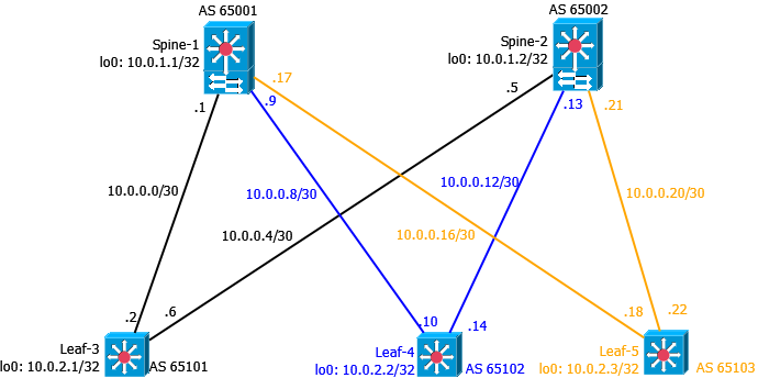
Schritt 1 - Einrichtung von IP-Adressen auf allen Komponenten
Spine-1
1
2
3
4
5
6
7
8
9
10
11
12
13
14
15
16
17
18
19
20
21
22
23
24
25
26
27
28
29
30
31
32
xe-0/0/0 {
    description Leaf-3--xe0/0/0;
    mtu 9216;
    unit 0 {
        family inet {
            mtu 9000;
            address 10.0.0.1/30;
        }
    }
}

xe-0/0/1 {
    description Leaf-4--xe0/0/0;
    mtu 9216;
    unit 0 {
        family inet {
            mtu 9000;
            address 10.0.0.9/30;
        }
    }
}

xe-0/0/2 {
    description Leaf-5--xe0/0/0;
    mtu 9216;
    unit 0 {
        family inet {
            mtu 9000;
            address 10.0.0.17/30;
        }
    }
}
Spine-2
1
2
3
4
5
6
7
8
9
10
11
12
13
14
15
16
17
18
19
20
21
22
23
24
25
26
27
28
29
30
31
32
xe-0/0/0 {
    description Leaf-3--xe0/0/1;
    mtu 9216;
    unit 0 {
        family inet {
            mtu 9000;
            address 10.0.0.5/30;
        }
    }
}

xe-0/0/1 {
    description Leaf-4--xe0/0/1;
    mtu 9216;
    unit 0 {
        family inet {
            mtu 9000;
            address 10.0.0.13/30;
        }
    }
}

xe-0/0/2 {
    description Leaf-5--x0/0/1;
    mtu 9216;
    unit 0 {
        family inet {
            mtu 9000;
            address 10.0.0.21/30;
        }
    }
}
Leaf-3
1
2
3
4
5
6
7
8
9
10
11
12
13
14
15
16
17
18
19
20
21
xe-0/0/0 {
    description Spine-1--xe0/0/0;
    mtu 9216;
    unit 0 {
        family inet {
            mtu 9000;
            address 10.0.0.2/30;
        }
    }
}

xe-0/0/1 {
    description Spine-2--xe0/0/0;
    mtu 9216;
    unit 0 {
        family inet {
            mtu 9000;
            address 10.0.0.6/30;
        }
    }
}
Leaf-4
1
2
3
4
5
6
7
8
9
10
11
12
13
14
15
16
17
18
19
20
21
xe-0/0/0 {
    description Spine-1--xe0/0/1;
    mtu 9216;
    unit 0 {
        family inet {
            mtu 9000;
            address 10.0.0.10/30;
        }
    }
}

xe-0/0/1 {
    description Spine-2--xe0/0/1;
    mtu 9216;
    unit 0 {
        family inet {
            mtu 9000;
            address 10.0.0.14/30;
        }
    }
}
Leaf-5
1
2
3
4
5
6
7
8
9
10
11
12
13
14
15
16
17
18
19
20
21
xe-0/0/0 {
    description Spine-1--xe0/0/2;
    mtu 9216;
    unit 0 {
        family inet {
            mtu 9000;
            address 10.0.0.18/30;
        }
    }
}

xe-0/0/1 {
    description Spine-2--xe0/0/2;
    mtu 9216;
    unit 0 {
        family inet {
            mtu 9000;
            address 10.0.0.22/30;
        }
    }
}
Schritt 2 - Konfiguration der Loopback-Interfaces
Spine-1
1
2
3
4
5
6
7
lo0 {
    unit 0 {
        family inet {
            address 10.0.1.1/32;
        }
    }
}
Spine-2
1
2
3
4
5
6
7
lo0 {
    unit 0 {
        family inet {
            address 10.0.1.2/32;
        }
    }
}
Leaf-3
1
2
3
4
5
6
7
lo0 {
    unit 0 {
        family inet {
            address 10.0.2.1/32;
        }
    }
}
Leaf-4
1
2
3
4
5
6
7
lo0 {
    unit 0 {
        family inet {
            address 10.0.2.2/32;
        }
    }
}
Leaf-5
1
2
3
4
5
6
7
lo0 {
    unit 0 {
        family inet {
            address 10.0.2.3/32;
        }
    }
}
Schritt 3 - Routing Optionen einstellen
Spine-1
1
2
3
4
5
6
7
routing-options {
router-id 10.0.1.1;
autonomous-system 65001;
forwarding-table {
    export pfe-ecmp;
    ecmp-fast-reroute;
}
Spine-2
1
2
3
4
5
6
7
routing-options {
router-id 10.0.1.2;
autonomous-system 65002;
forwarding-table {
    export pfe-ecmp;
    ecmp-fast-reroute;
}
Leaf-3
1
2
3
4
5
6
7
routing-options {
router-id 10.0.2.1;
autonomous-system 65101;
forwarding-table {
    export pfe-ecmp;
    ecmp-fast-reroute;
}
Leaf-4
1
2
3
4
5
6
7
routing-options {
router-id 10.0.2.2;
autonomous-system 65102;
forwarding-table {
    export pfe-ecmp;
    ecmp-fast-reroute;
}
Leaf-5
1
2
3
4
5
6
7
routing-options {
router-id 10.0.2.3;
autonomous-system 65103;
forwarding-table {
    export pfe-ecmp;
    ecmp-fast-reroute;
}
Schritt 4 - Routing konfigurieren
Für die BGP Konfiguration wird die Gruppe “dc” erstellt. Jedes Gerät hat seine eigene AS Nummer. Um Ausfälle schneller zu erkennen, wird BFD verwendet. Die Prefixe, welche gelernt und propagiert werden, werden per Policy bestimmt.
Spine-1
1
2
3
4
5
6
7
8
9
10
11
12
13
14
15
16
17
18
19
20
21
22
23
24
25
26
27
28
29
30
bgp {
    log-updown;
    import bgp-in;
    export bgp-out;
    graceful-restart;
    bfd-liveness-detection {
        minimum-interval 350;
        multiplier 3;
        session-mode automatic;
    }
    group dc {
        type external;
        mtu-discovery;
        bfd-liveness-detection {
            minimum-interval 350;
            multiplier 3;
            session-mode single-hop;
        }
        multipath multiple-as;
        neighbor 10.0.0.2 {
            peer-as 65101;
        }
        neighbor 10.0.0.10 {
            peer-as 65102;
        }
        neighbor 10.0.0.18 {
            peer-as 65103;
        }
    }
}
Spine-2
1
2
3
4
5
6
7
8
9
10
11
12
13
14
15
16
17
18
19
20
21
22
23
24
25
26
27
28
29
bgp {
    log-updown;
    import bgp-in;
    export bgp-out;
    graceful-restart;
    bfd-liveness-detection {
        minimum-interval 350;
        multiplier 3;
        session-mode automatic;
    }
    group dc {
        type external;
        mtu-discovery;
        bfd-liveness-detection {
            minimum-interval 350;
            multiplier 3;
        }
        multipath multiple-as;
        neighbor 10.0.0.6 {
            peer-as 65101;
        }
        neighbor 10.0.0.14 {
            peer-as 65102;
        }
        neighbor 10.0.0.22 {
            peer-as 65103;
        }
    }
}
Leaf-3
1
2
3
4
5
6
7
8
9
10
11
12
13
14
15
16
17
18
19
20
21
22
23
24
25
26
27
bgp {
    log-updown;
    import bgp-in;
    export bgp-out;
    graceful-restart;
    bfd-liveness-detection {
        minimum-interval 350;
        multiplier 3;
        session-mode automatic;
    }
    group dc {
        type external;
        mtu-discovery;
        bfd-liveness-detection {
            minimum-interval 350;
            multiplier 3;
            session-mode single-hop;
        }
        multipath multiple-as;
        neighbor 10.0.0.1 {
            peer-as 65001;
        }
        neighbor 10.0.0.5 {
            peer-as 65002;
        }
    }
}
Leaf-4
1
2
3
4
5
6
7
8
9
10
11
12
13
14
15
16
17
18
19
20
21
22
23
24
25
26
bgp {
    log-updown;
    import bgp-in;
    export bgp-out;
    graceful-restart;
    bfd-liveness-detection {
        minimum-interval 350;
        multiplier 3;
        session-mode automatic;
    }
    group dc {
        type external;
        mtu-discovery;
        bfd-liveness-detection {
            minimum-interval 350;
            multiplier 3;
        }
        multipath multiple-as;
        neighbor 10.0.0.13 {
            peer-as 65002;
        }
        neighbor 10.0.0.9 {
            peer-as 65001;
        }
    }
}
Leaf-5
1
2
3
4
5
6
7
8
9
10
11
12
13
14
15
16
17
18
19
20
21
22
23
24
25
26
27
bgp {
    log-updown;
    import bgp-in;
    export bgp-out;
    graceful-restart;
    bfd-liveness-detection {
        minimum-interval 350;
        multiplier 3;
        session-mode automatic;
    }
    group dc {
        type external;
        mtu-discovery;
        bfd-liveness-detection {
            minimum-interval 350;
            multiplier 3;
            session-mode single-hop;
        }
        multipath multiple-as;
        neighbor 10.0.0.17 {
            peer-as 65001;
        }
        neighbor 10.0.0.21 {
            peer-as 65002;
        }
    }
}
Schritt 5 - Policies einrichten
Die Policies sind auf allen Geräten gleich. Bei Juniper sind Policies leicht lesbar und mittels “term” können sinnvolle Bezeichnungen verwendet werden.
1
2
3
4
5
6
7
8
9
10
11
12
13
14
15
16
17
18
19
20
21
22
23
24
policy-statement bgp-in {
    term loopbacks {
        from {
            route-filter 10.0.1.0/24 orlonger;
            route-filter 10.0.2.0/24 orlonger;
        }
        then accept;
    }
    term leaf-layer3 {
        from {
            route-filter 10.10.0.0/16 orlonger;
        }
        then accept;
    }
    term transit {
        from {
            route-filter 10.0.0.0/24 orlonger;
        }
        then accept;
    }
    term reject {
        then reject;
    }
}
bgp-in erlaubt den Import (oder die Annahme / das Lernen) von Loopback-Adressen (Spine und Leaf), Rechnernetze (10.10.x.y) und sämtliche Transitnetze. Dies wird durch den Router-Filter ermöglicht. Alles andere wird verworfen.
1
2
3
4
5
6
7
8
9
10
11
12
13
14
15
16
17
18
19
20
21
22
23
24
25
26
policy-statement bgp-out {
    term loopback {
        from {
            protocol direct;
            route-filter 10.0.1.0/24 orlonger;
        }
        then accept;
    }
    term leaf-layer3 {
        from {
            protocol direct;
            route-filter 10.10.0.0/16 orlonger;
        }
        then {
            next-hop self;
            accept;
        }
    }
    term transit {
        from {
            protocol direct;
            route-filter 10.0.0.0/24 orlonger;
        }
        then accept;
    }
}
bgp-out redistributiert die direkt angeschlossenen Netze. Unter Cisco nennt sich das redistribute connected. Durch den Route-Filter werden nur Loopback, Server- und Transitnetze erlaubt.
1
2
3
4
5
policy-statement pfe-ecmp {
    then {
        load-balance per-packet;
    }
}
pfe-ecmp erlaubt Equal Cost Multipath, was im Normalfall bei BGP nicht möglich ist.
Jetzt kann die Konfiguration mittels commit check auf Fehler geprüft werden. Sollten keine Fehler auftreten, kann die Konfiguration per commit aktiviert werden. Anschließend sollten sich BGP Sessions aufbauen.
Beispiel Leaf-5:
1
2
3
4
5
6
7
8
root@Leaf-5> show bgp summary
Groups: 1 Peers: 2 Down peers: 0
Table          Tot Paths  Act Paths Suppressed    History Damp State    Pending
inet.0
                      20         12          0          0          0          0
Peer                     AS      InPkt     OutPkt    OutQ   Flaps Last Up/Dwn State|#Active/Received/Accepted/Damped...
10.0.0.17             65001         54         50       0       1       18:44 6/10/10/0            0/0/0/0
10.0.0.21             65002         62         56       0       0       22:33 6/10/10/0            0/0/0/0
Beispiel Spine-2:
1
2
3
4
5
6
7
8
9
root@Spine-2> show bgp summary
Groups: 1 Peers: 3 Down peers: 0
Table          Tot Paths  Act Paths Suppressed    History Damp State    Pending
inet.0
                      22         10          0          0          0          0
Peer                     AS      InPkt     OutPkt    OutQ   Flaps Last Up/Dwn State|#Active/Received/Accepted/Damped...
10.0.0.6              65101         90         86       0       0       34:44 4/8/8/0              0/0/0/0
10.0.0.14             65102         76         83       0       0       30:48 3/8/8/0              0/0/0/0
10.0.0.22             65103         57         64       0       0       22:57 3/6/6/0              0/0/0/0
Die Routingtabelle von Leaf-5 sieht jetzt folgendermaßen aus:
1
2
3
4
5
6
7
8
9
10
11
12
13
14
15
16
17
18
19
20
21
22
23
24
25
26
27
28
29
30
31
32
33
34
35
36
37
38
39
40
41
42
43
44
45
46
47
48
49
50
51
52
53
54
55
56
57
58
59
60
61
62
63
64
65
66
67
68
69
70
71
72
73
74
75
76
77
78
79
80
81
82
83
84
85
86
87
88
89
90
91
92
93
94
95
96
97
98
99
100
101
102
103
104
105
106
107
108
109
110
111
112
113
114
115
116
117
118
119
120
121
122
123
root@Leaf-5> show route

inet.0: 16 destinations, 27 routes (16 active, 0 holddown, 0 hidden)
+ = Active Route, - = Last Active, * = Both

10.0.0.0/30        *[BGP/170] 00:14:06, localpref 100
                      AS path: 65001 I, validation-state: unverified
                    > to 10.0.0.17 via xe-0/0/0.0
                    [BGP/170] 00:04:12, localpref 100
                      AS path: 65002 65101 I, validation-state: unverified
                    > to 10.0.0.21 via xe-0/0/1.0
10.0.0.4/30        *[BGP/170] 00:05:48, localpref 100
                      AS path: 65002 I, validation-state: unverified
                    > to 10.0.0.21 via xe-0/0/1.0
                    [BGP/170] 00:04:12, localpref 100
                      AS path: 65001 65101 I, validation-state: unverified
                    > to 10.0.0.17 via xe-0/0/0.0
10.0.0.8/30        *[BGP/170] 00:14:06, localpref 100
                      AS path: 65001 I, validation-state: unverified
                    > to 10.0.0.17 via xe-0/0/0.0
                    [BGP/170] 00:02:03, localpref 100
                      AS path: 65002 65102 I, validation-state: unverified
                    > to 10.0.0.21 via xe-0/0/1.0
10.0.0.12/30       *[BGP/170] 00:05:48, localpref 100
                      AS path: 65002 I, validation-state: unverified
                    > to 10.0.0.21 via xe-0/0/1.0
                    [BGP/170] 00:02:03, localpref 100
                      AS path: 65001 65102 I, validation-state: unverified
                    > to 10.0.0.17 via xe-0/0/0.0
10.0.0.16/30       *[Direct/0] 3d 01:09:32
                    > via xe-0/0/0.0
                    [BGP/170] 00:14:06, localpref 100
                      AS path: 65001 I, validation-state: unverified
                    > to 10.0.0.17 via xe-0/0/0.0
10.0.0.18/32       *[Local/0] 3d 01:09:32
                      Local via xe-0/0/0.0
10.0.0.20/30       *[Direct/0] 3d 01:09:32
                    > via xe-0/0/1.0
                    [BGP/170] 00:05:48, localpref 100
                      AS path: 65002 I, validation-state: unverified
                    > to 10.0.0.21 via xe-0/0/1.0
10.0.0.22/32       *[Local/0] 3d 01:09:32
                      Local via xe-0/0/1.0
10.0.1.1/32        *[BGP/170] 00:17:39, localpref 100
                      AS path: 65001 I, validation-state: unverified
                    > to 10.0.0.17 via xe-0/0/0.0
                    [BGP/170] 00:21:28, localpref 100
                      AS path: 65002 65101 65001 I, validation-state: unverified
                    > to 10.0.0.21 via xe-0/0/1.0
10.0.1.2/32        *[BGP/170] 00:21:28, localpref 100
                      AS path: 65002 I, validation-state: unverified
                    > to 10.0.0.21 via xe-0/0/1.0
                    [BGP/170] 00:17:39, localpref 100
                      AS path: 65001 65101 65002 I, validation-state: unverified
                    > to 10.0.0.17 via xe-0/0/0.0
10.0.2.1/32        *[BGP/170] 00:21:28, localpref 100, from 10.0.0.21
                      AS path: 65002 65101 I, validation-state: unverified
                    > to 10.0.0.17 via xe-0/0/0.0
                      to 10.0.0.21 via xe-0/0/1.0
                    [BGP/170] 00:17:39, localpref 100
                      AS path: 65001 65101 I, validation-state: unverified
                    > to 10.0.0.17 via xe-0/0/0.0
10.0.2.2/32        *[BGP/170] 00:21:28, localpref 100
                      AS path: 65002 65102 I, validation-state: unverified
                      to 10.0.0.17 via xe-0/0/0.0
                    > to 10.0.0.21 via xe-0/0/1.0
                    [BGP/170] 00:17:39, localpref 100
                      AS path: 65001 65102 I, validation-state: unverified
                    > to 10.0.0.17 via xe-0/0/0.0
10.0.2.3/32        *[Direct/0] 3d 00:36:48
                    > via lo0.0
10.10.100.0/24     *[BGP/170] 00:21:28, localpref 100, from 10.0.0.21
                      AS path: 65002 65101 I, validation-state: unverified
                    > to 10.0.0.17 via xe-0/0/0.0
                      to 10.0.0.21 via xe-0/0/1.0
                    [BGP/170] 00:17:39, localpref 100
                      AS path: 65001 65101 I, validation-state: unverified
                    > to 10.0.0.17 via xe-0/0/0.0
169.254.0.0/24     *[Direct/0] 3d 02:54:35
                    > via em1.0
169.254.0.2/32     *[Local/0] 3d 02:54:35
                      Local via em1.0

inet6.0: 1 destinations, 1 routes (1 active, 0 holddown, 0 hidden)
+ = Active Route, - = Last Active, * = Both

fe80::200:f:fc00:0/128
                   *[Direct/0] 3d 02:54:35
                    > via lo0.0


Somit ist die grundsätzliche Erreichbarkeit gegeben.

Auf Leaf-3 kann jetzt ein Testnetz angelegt werden, in dem sich ein Rechner befindet.

```bash
irb {
    unit 100 {
        family inet {
            address 10.10.100.1/24;
        }
    }
}

vlans {
    default {
        vlan-id 1;
    }
    net100 {
        vlan-id 100;
        l3-interface irb.100;
    }
}

xe-0/0/10 {
    unit 0 {
        family ethernet-switching {
            vlan {
                members net100;
            }
        }
    }
}
Ping vom PC funktionieren zum Spine-1:
1
2
3
4
5
6
7
8
9
10
11
12
13
14
15
16
17
18
19
100-1> ping 10.0.1.1

84 bytes from 10.0.1.1 icmp_seq=1 ttl=63 time=77.695 ms
84 bytes from 10.0.1.1 icmp_seq=2 ttl=63 time=38.227 ms
84 bytes from 10.0.1.1 icmp_seq=3 ttl=63 time=54.859 ms
84 bytes from 10.0.1.1 icmp_seq=4 ttl=63 time=39.366 ms
84 bytes from 10.0.1.1 icmp_seq=5 ttl=63 time=87.726 ms


100-1> trace 10.0.1.1
trace to 10.0.1.1, 8 hops max, press Ctrl+C to stop
 1   10.10.100.1   29.302 ms  16.281 ms  17.379 ms
 2   *10.0.1.1   38.202 ms (ICMP type:3, code:3, Destination port unreachable)

100-1> trace 10.0.2.3
trace to 10.0.2.3, 8 hops max, press Ctrl+C to stop
 1   10.10.100.1   21.741 ms  166.414 ms  42.807 ms
 2   10.0.0.1   49.569 ms  35.330 ms  36.244 ms
 3   *10.0.2.3   69.785 ms (ICMP type:3, code:3, Destination port unreachable)
Damit ist die Konfiguration fertig.