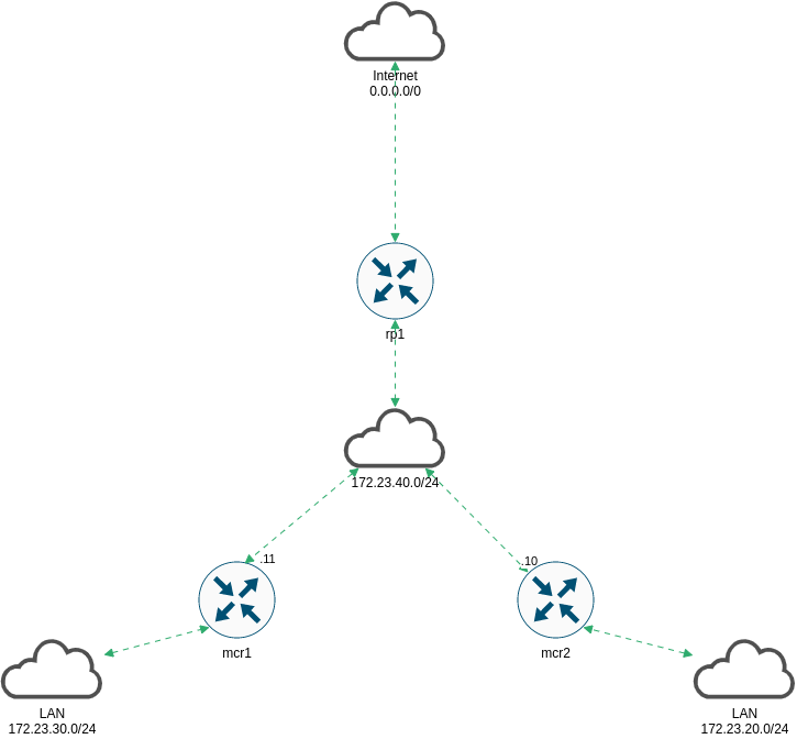
VyOS ist in der Lage Multicast zu routen. Es wird PIM Sparde Mode, IGMP und IGMP-Proxy unterstützt. Im folgenden Beispiel soll Multicast über den
Rendevouz Point rp1 gesteuert werden.
Folgende Topologie wird verwendet:

Basics
Im ersten Schritt werden die Netzwerkkarten eingerichtet. Alle Router erhalten eine Adresse im Managementnetz, eine Adresse in Richtung Internet und eine “Adresse” für das LAN.
mcr1
1
2
3
4
5
6
7
8
9
10
11
12
13
14
15
16
17
18
| vyos@mcr1# show interfaces
ethernet eth0 {
address 172.23.40.11/24
description "-> ISP"
hw-id 00:0c:29:0f:32:0b
}
ethernet eth1 {
address 10.10.10.111/24
description MGM
hw-id 00:0c:29:0f:32:15
}
ethernet eth2 {
address 172.23.20.10/24
description LAN
hw-id 00:0c:29:0f:32:1f
}
loopback lo {
}
|
mcr2
1
2
3
4
5
6
7
8
9
10
11
12
13
14
15
16
17
18
| vyos@mcr2# show interfaces
ethernet eth0 {
address 172.23.40.12/24
description "-> ISP"
hw-id 00:0c:29:5a:17:8d
}
ethernet eth1 {
address 10.10.10.112/24
description MGM
hw-id 00:0c:29:5a:17:97
}
ethernet eth2 {
address 172.23.30.10/24
description LAN
hw-id 00:0c:29:5a:17:a1
}
loopback lo {
}
|
rp1
1
2
3
4
5
6
7
8
9
10
11
12
13
14
15
16
17
18
| vyos@rp1# show interfaces
ethernet eth0 {
address dhcp
description Internet
hw-id 00:0c:29:de:43:d5
}
ethernet eth1 {
address 10.10.10.113/24
description MGM
hw-id 00:0c:29:de:43:df
}
ethernet eth2 {
address 172.23.40.100/24
description Transit
hw-id 00:0c:29:de:43:e9
}
loopback lo {
}
|
Dynamisches Routing mit IS-IS
Die Router sind soweit eingerichtet, allerdings haben mcr1 und mcr2 keinen Zugriff ins Internet. Ferner wird die PIM-RP Adresse noch nicht erreicht.
Damit keine statischen Routen eingerichtet werden müssen, werden die Netze
dynamisch geroutet. Als Protokoll kommt heute IS-IS zum Einsatz.
Der Designierte IS wird rp1. Als net Adresse wird das Schema
49.Area-ID.Router.Loopback.IP.00 verwendet. Zur Authentifizierung wird ein Passwort gesetzt, nicht benötigte Interfaces sind passiv.
Die Router werden als Level-1 eingerichtet, da sie nur Nachbarn in der gleichen Area haben und nur Routinginformationen über diese eine Area benötigen.
Konfiguration rp1
1
2
3
4
5
| vyos@rp1# show interfaces loopback
loopback lo {
address 192.168.100.1/32
description Loopback
}
|
1
2
3
4
5
6
7
8
9
10
11
12
13
14
15
16
17
18
19
20
21
22
23
24
25
26
27
| vyos@rp1# sh
default-information {
originate {
ipv4 {
level-1 {
}
}
}
}
interface eth0 {
passive
}
interface eth1 {
passive
}
interface eth2 {
password {
plaintext-password 12341234
}
}
interface lo {
passive
}
level level-1
log-adjacency-changes
metric-style wide
net 49.0023.1921.6810.0001.00
|
Konfiguration mcr1
1
2
3
4
5
| vyos@mcr1# show interfaces loopback
loopback lo {
address 192.168.210.1/32
description Loopback
}
|
1
2
3
4
5
6
7
8
9
10
11
12
13
14
15
16
17
18
19
20
| vyos@mcr1# show protocols isis
interface eth0 {
password {
plaintext-password 12341234
}
priority 0
}
interface eth1 {
passive
}
interface eth2 {
passive
}
interface lo {
passive
}
level level-1
log-adjacency-changes
metric-style wide
net 49.0023.1921.6821.0001.00
|
Konfiguration mcr2
1
2
3
4
5
| vyos@mcr2# show interfaces loopback
loopback lo {
address 192.168.220.1/32
description Loopback
}
|
1
2
3
4
5
6
7
8
9
10
11
12
13
14
15
16
17
18
19
20
| vyos@mcr2# show protocols isis
interface eth0 {
password {
plaintext-password 12341234
}
priority 0
}
interface eth1 {
passive
}
interface eth2 {
passive
}
interface lo {
passive
}
level level-1
log-adjacency-changes
metric-style wide
net 49.0023.1921.6822.0001.00
|
Anschließend sollten in der Routingtabelle IS-IS Routen auftauchen.
1
2
3
4
5
6
7
8
9
10
11
12
13
14
15
16
17
| vyos@mcr2# run sh ip route isis
Codes: K - kernel route, C - connected, S - static, R - RIP,
O - OSPF, I - IS-IS, B - BGP, E - EIGRP, N - NHRP,
T - Table, v - VNC, V - VNC-Direct, A - Babel, F - PBR,
f - OpenFabric,
> - selected route, * - FIB route, q - queued, r - rejected, b - backup
t - trapped, o - offload failure
I>* 0.0.0.0/0 [115/10] via 172.23.40.100, eth0, weight 1, 00:01:12
I 10.10.10.0/24 [115/20] via 172.23.40.11, eth0, weight 1, 00:01:12
via 172.23.40.100, eth0, weight 1, 00:01:12
I>* 10.23.4.0/23 [115/20] via 172.23.40.100, eth0, weight 1, 00:01:12
I>* 172.23.20.0/24 [115/20] via 172.23.40.11, eth0, weight 1, 00:01:12
I 172.23.40.0/24 [115/20] via 172.23.40.11, eth0 inactive, weight 1, 00:01:12
via 172.23.40.100, eth0 inactive, weight 1, 00:01:12
I>* 192.168.100.1/32 [115/20] via 172.23.40.100, eth0, weight 1, 00:01:12
I>* 192.168.210.1/32 [115/20] via 172.23.40.11, eth0, weight 1, 00:01:12
|
Multicast (PIM) einrichten
Auf allen Interfaces zum und vom RP wird PIM aktiviert. Auf Interfaces, die mit Clients in Kontakt kommen können, wird zusätzlich IGMP aktiviert. Der RP benötigt hier im Beispiel kein IGMP.
Konfiguration mcr1
1
2
3
4
5
6
7
8
9
10
| vyos@mcr1# show protocols pim
interface eth0 {
}
interface eth2 {
}
rp {
address 192.168.255.1 {
group 224.0.0.0/4
}
}
|
1
2
3
| vyos@mcr1# show protocols igmp
interface eth2 {
}
|
Konfiguration mcr2
1
2
3
4
5
6
7
8
9
10
| vyos@mcr1# show protocols pim
interface eth0 {
}
interface eth2 {
}
rp {
address 192.168.255.1 {
group 224.0.0.0/4
}
}
|
1
2
3
| vyos@mcr1# show protocols igmp
interface eth2 {
}
|
Konfiguration rp1
1
2
3
4
5
| vyos@rp1# show interfaces dummy
dummy dum0 {
address 192.168.255.1/32
description "RP Interface"
}
|
1
2
3
4
5
6
7
8
9
10
11
12
| vyos@rp1# show protocols pim
interface dum0 {
}
interface eth1 {
}
interface eth2 {
}
rp {
address 192.168.255.1 {
group 224.0.0.0/4
}
}
|
Die Adresse vom Dummy Interface gelangt nicht automatisch in den Routingprozess, daher wird die IP 192.168.255.1 ins IS-IS redistributiert.
1
2
3
4
5
6
7
8
9
10
11
12
13
14
15
16
17
18
19
20
| vyos@rp1# show policy
prefix-list dummy-into-isis {
rule 5 {
action permit
prefix 192.168.255.1/32
}
}
route-map dummy-into-isis {
description "Multicast Interface into ISIS"
rule 5 {
action permit
match {
ip {
address {
prefix-list dummy-into-isis
}
}
}
}
}
|
1
2
3
4
5
6
7
8
| vyos@rp1# show protocols isis redistribute
ipv4 {
connected {
level-1 {
route-map dummy-into-isis
}
}
}
|
Jetzt sollte die Adresse in der Routingtabelle von mcr1 und mcr2 auftauchen.
1
2
3
4
5
| vyos@mcr1# run show ip route 192.168.255.1
Routing entry for 192.168.255.1/32
Known via "isis", distance 115, metric 10, best
Last update 00:04:20 ago
* 172.23.40.100, via eth0, weight 1
|
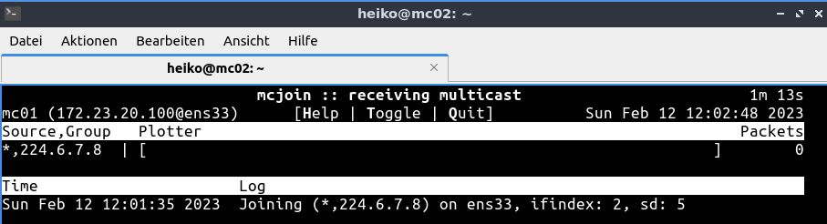
Multicast Traffic erzeugen
Multicast Traffic wird auf zwei debian Systemen über das Tool mcjoin erzeugt.
1
| root@mc01:/opt/mcjoin/bin# ./mcjoin -s 224.6.7.8
|

Der Client taucht auf dem RP auf:
1
2
3
| yos@rp1:~$ sh ip pim join
Interface Address Source Group State Uptime Expire Prune
eth2 172.23.40.100 * 224.6.7.8 JOIN 00:01:49 03:10 --:--
|
1
2
3
| vyos@rp1:~$ sh ip pim upstream
Iif Source Group State Uptime JoinTimer RSTimer KATimer RefCnt
dum0 * 224.6.7.8 J 00:02:06 00:00:53 --:--:-- --:--:-- 1
|
Auf dem zweiten Client wird ebenfalls mcjoin aktiviert.
1
| root@mc02:/opt/mcjoin/bin# ./mcjoin -s 225.6.7.8
|
Dieser taucht ebenfalls auf dem RP auf.
1
2
3
4
| vyos@rp1:~$ sh ip pim join
Interface Address Source Group State Uptime Expire Prune
eth2 172.23.40.100 * 224.6.7.8 JOIN 00:05:08 02:50 --:--
eth2 172.23.40.100 * 225.6.7.8 JOIN 00:00:26 03:03 --:--
|
1
2
3
4
5
| vyos@rp1:~$ sh ip pim upstream
Iif Source Group State Uptime JoinTimer RSTimer KATimer RefCnt
eth2 172.23.30.128 224.1.2.3 NotJ 00:06:08 00:00:00 --:--:-- 00:01:22 1
dum0 * 224.6.7.8 J 00:06:28 00:00:31 --:--:-- --:--:-- 1
dum0 * 225.6.7.8 J 00:01:46 00:00:13 --:--:-- --:--:-- 1
|
Damit arbeitet das Multicast Routing.